Showing posts with label lone pairs. Show all posts

Sunday, March 27, 2022

Chapter 12.16 - Resonance Effect

In the previous section, we saw the details about stability of resonance structures. In this section, we will see resonance effect.

• We know that inorganic molecules like HCl are polar.
    ♦ The Cl atom being electronegative, pulls the electron density in the covalent bond.
    ♦ This gives Cl a partial -ve charge. Also H gets a partial +ve charge.
    ♦ See section 4.10.
• Some organic molecules are also polar. This can be demonstrated using two examples.

Example 1:
In this example, we analyze the resonance structures of aniline. It can be written in 6 steps:
1. The structure I of fig.12.101 below shows aniline. In this structure, all the atoms have octet.


Positive resonance effect (+R effect) in aniline.
Fig.12.101

• The structure II is obtained by rearranging the electrons present in I
• In I, NㅡC1 is a single bond. But this same NㅡC1 becomes a double bond in II.
• This is because of the movement of electrons indicated by the green curved-arrow.
   ♦ Two electrons from the lone pair of N moves to NㅡC1
   ♦ Those two electrons were singly-owned by N.
   ♦ After the formation of N=C1, the N co-owns those electrons.
   ♦ So N does not lose any electrons.
• So due to the green curved-arrow,
   ♦ N does not lose any electrons.
   ♦ C1 gains two electrons.
• Note the + formal charge of N in II. This can be explained in 3 steps:
(i) An independent N atom will have five electrons around it.
(ii) But in II, there are only four electrons around N.
    ♦ Two from the bonds with the H atoms.
    ♦ Two from the double bond.
(iii) That means, N has lost an electron. Thus it gains one +ve formal charge. 
• Due to the green curved-arrow in I, C1 now possess two new electrons.
• But C1 already has octet. It does not need any electrons.
• So the magenta curved-arrow comes into play.
   ♦ Two electrons in C1=C2 moves to C2
   ♦ They become a lone pair of C2
• Thus the two unwanted electrons gained by C1 through the green curved-arrow, are lost by the action of magenta curved arrow.
• Note the - formal charge of C2 in II. This can be explained in 3 steps:
(i) An independent C atom will have four electrons around it.
(ii) But in II, there are five electrons around C2
    ♦ Two from the lone pair.
    ♦ One from C2ㅡC1
    ♦ One from C2ㅡC3
    ♦ One from C2ㅡH
(iii) That means, C2 has gained an electron. Thus it gains one -ve formal charge. 
2. From the above step (1), we know how structure II is formed. So let us analyze the curved-arrows in structure II
• The C2 in II has two unwanted electrons. So the yellow curved-arrow comes into play.
    ♦ The lone pair of C2 moves to C2ㅡC3.
    ♦ Thus C2ㅡC3  becomes C2=C3.
    ♦ This double bond is shown in III
• When such a double bond is formed, C3 will have two unwanted electrons.
    ♦ So the cyan curved-arrow comes into play.
    ♦ Two electrons in C3=C4 moves to C4
    ♦ They become a lone pair of C4
• Thus the two unwanted electrons gained by C3 through the yellow curved-arrow, are lost by the action of cyan curved arrow.
• Note the - formal charge of C4 in III. This can be explained in 3 steps:
(i) An independent C atom will have four electrons around it.
(ii) But in II, there are five electrons around C4
    ♦ Two from the lone pair.
    ♦ One from C4ㅡC3
    ♦ One from C4ㅡC5
    ♦ One from C4ㅡH
(iii) That means, C4 has gained an electron. Thus it gains one -ve formal charge.
3. From the above step (2), we know how structure III is formed. We can write similar steps to analyze the curved-arrows in structure III.
• Based on those steps, we would see how structure IV is formed.
• The reader is advised to write those steps in his/her own notebook.
4. In effect, we see that:
• Structure I is neutral.
• Structures II, III and IV are not neutral. They are charged.
    ♦ This is due to the movement of electrons as indicated by the curved arrows.
    ♦ Positions with -ve formal charge have high electron densities.
    ♦ Positions with +ve formal charge have low electron densities.
5. So one contributing structure is neutral while the remaining three contributing structures are charged.
• So the hybrid structure will be charged. That means, in a sample of aniline, the molecules will exist in a charged state. This is just like charged molecules in a sample of HCl.
6. In this example, the electrons are transferred away from the substituent group (ㅡNH2 group).
• If the transfer of electrons is away from an atom or substituent group attached to the conjugated system, it is known as positive resonance effect (+R effect)
• A conjugated system is that system in which single bonds and double bonds occur in an alternating arrangement.

Example 2:
In this example, we analyze the resonance structures of nitrobenzene. It can be written in 6 steps:
1. The structure I of fig.12.102 below shows nitrobenzene. In this structure, all the atoms have octet.

Negative resonance effect in nitrobenzene.
Fig.12.102

• The arrow between N and O indicates that, the bond between N and that O is a coordinate bond. Both electrons in that bond originally belonged to N. However, that coordinate bond has no role in our present discussion.
• The structure II is obtained by rearranging the electrons present in I
• Consider the N=O double bond in I. This same N=O becomes a single bond in II.
• This is because of the movement of electrons indicated by the green curved-arrow.
   ♦ Two electrons in the N=O moves to O.
   ♦ They become a lone pair of O
• Due to this movement of electrons, N has lost two electrons. So the magenta curved-arrow comes into play.
   ♦ Two electrons in C1=C2 moves to NㅡC1
   ♦ Thus C1=C2 becomes C1ㅡC2 and NㅡC1 becomes N=C1
• Note the - formal charge of O in II. This can be explained in 3 steps:
(i) An independent O atom will have six electrons around it.
(ii) But in II, there are seven electrons around that O
    ♦ Six from three lone pairs.
    ♦ One from NㅡO
(iii) That means, O has gained an electron. Thus it gains one -ve formal charge.
• Note the + formal charge of C2 in II. This can be explained in 3 steps:
(i) An independent C atom will have four electrons around it.
(ii) But in II, there are only three electrons around C2.
    ♦ One from bond with the H atom.
    ♦ One from C2ㅡC1
    ♦ One from C2ㅡC3
(iii) That means, C2 has lost an electron. Thus it gains one +ve formal charge. 
• Thus the two electrons lost by N through the green curved-arrow, are gained by the action of magenta curved arrow.
2. From the above step (1), we know how structure II is formed. So let us analyze the curved-arrow in structure II
• The C2 in II needs two electrons. So the yellow curved-arrow comes into play.
   ♦ Two electrons in C3=C4 moves to C2ㅡC3
   ♦ Thus C3=C4 becomes C3ㅡC4 and C2ㅡC3 becomes C2=C3.
   ♦ This is shown in III.
• Note the + formal charge of C4 in III. This can be explained in 3 steps:
(i) An independent C atom will have four electrons around it.
(ii) But in III, there are only three electrons around C4.
    ♦ One from bond with the H atom.
    ♦ One from C4ㅡC3
    ♦ One from C4ㅡC5
(iii) That means, C4 has lost an electron. Thus it gains one +ve formal charge. 
3. From the above step (2), we know how structure III is formed. We can write similar steps to analyze the curved-arrow in structure III.
• Based on those steps, we would see how structure IV is formed.
• The reader is advised to write those steps in his/her own notebook.
4. In effect, we see that:
• Structure I is neutral.
• Structures II, III and IV are not neutral. They are charged.
    ♦ This is due to the movement of electrons as indicated by the curved arrows.
    ♦ Positions with -ve formal charge have high electron densities.
    ♦ Positions with +ve formal charge have low electron densities.
5. So one contributing structure is neutral while the remaining three contributing structures are charged.
• So the hybrid structure will be charged. That means, in a sample of nitrobenzene, the molecules will exist in a charged state. This is just like charged molecules in a sample of HCl.
6. In this example, the electrons are transferred towards the substituent group (ㅡNO2 group).
• If the transfer of electrons is towards an atom or substituent group attached to the conjugated system, it is known as negative resonance effect (-R effect).


◼ Note that:
• In example 1 (+R effect), the C atoms in the chain acquired greater electron densities. This is because of the movement of electrons away from the substituent group.
• In example 2 (-R effect), the C atoms in the chain lost electron densities. This is because of the movement of electrons towards the substituent group.


• The atoms or substituent groups which cause +R effect are:
ㅡ halogen, ㅡOH, ㅡOR, ㅡOCOR, ㅡNH2, ㅡNHR, ㅡNR2, ㅡNHCOR
• The atoms or substituent groups which cause -R effect are:
ㅡCOOH, ㅡCHO, >C=O, ㅡCN, ㅡNO2


• As mentioned before, the resonance effect (+R effect and -R effect) occur in conjugated systems. In conjugated systems, single bonds and double bonds in the chain are present in an alternating arrangement.
• Benzene and substituted benzene compounds are examples of a closed chain conjugated system.
• 1,3-butadiene is an example of an open chain conjugated system. It’s condensed formula is shown below:
CH3=CH2ㅡCH2=CH3


◼ Why is it that, the conjugated systems are subjected to +R effect and -R effects ?
• The answer can be written in 3 steps:
1. We know that, in a double bond, there is a 𝜎 bond and a π bond.
• In a 𝜎 bond, there is linear overlap of orbitals. The electrons are locked in position.
• But in a π bond, there is lateral overlap of orbitals. So the electrons are free to move.
2. So the electrons of the π bond move towards an adjacent single bond. That single bond will then become a double bond. We indicated such movements using curved-arrows in the above examples.
• The electrons of the π bond can also move towards an adjacent atom. Those atoms will then become regions of high electron densities. We indicated such movements also using curved-arrows in the above examples.
3. Regions of ‘electron richness’ and ‘electron deficiency’, will make the molecule polar.


In the next section we will see electromeric effect.


Previous

Contents

Next

Copyright©2022 Higher secondary chemistry.blogspot.com

Saturday, March 19, 2022

Chapter 12.15 - Relative Stability of Resonance Structures

In the previous section, we saw the basics about resonance in organic molecules. In this section, we will see how to compare various resonance structures of a molecule.

Rule 1:
    ♦ The resonance structure which has more number of covalent bonds
    ♦ is more stable than
    ♦ The resonance structure which has lesser number of covalent bonds.
• For calculating the number of covalent bonds, a double bond is considered as two bonds. A triple bond is considered as three bonds.
• An example is shown in fig.12.92 below.

Fig.12.92

• This can be explained in 4 steps:
(i) I and II are resonance structures of the same molecule.
• In I, the number of bonds is four. But in II, the number of bonds is three.
• So I will be more stable than II
(ii) Consequently, the hybrid structure will have a greater resemblance to I than II.
• We can say:
Structure I will contribute more towards the hybrid structure.
(iii) Let us check the formal charges. We have seen how to calculate formal charges in section 4.4.
We know that, any independent O atom will have six valence electrons.
• In I, we see that, the bottom O atom has gained an electron.
    ♦ That means, O has gained a -ve charge.
    ♦ Thus the formal charge of that O is ‘-’.
• In II, we see that, both top O and bottom O has gained an electron each.
    ♦ That means, those O atoms have gained a -ve charge each.
    ♦ Thus the formal charge of each of those O atoms is ‘-’.
(iv) We know that, any independent C atom will have four valence electrons.
• In II, we see that, the C atom has lost an electron.
    ♦ That means, C has gained a +ve charge.
    ♦ Thus the formal charge of that C is ‘+’.

Rule 2:
    ♦ The resonance structure in which all atoms have octet
    ♦ is more stable than
    ♦ The resonance structure in which one or more atoms have incomplete octet.
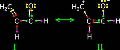
• An example is shown in fig.12.93 below.

Rules for comparing stability of resonance structures.
Fig.12.93

This can be explained in 3 steps:
(i) I and II are resonance structures of the same molecule.
• In I, all atoms have octet.
• In II, the C atom has only six electrons around it.
• So I will be more stable than II
(ii) Consequently, the hybrid structure will have a greater resemblance to I than II.
• We can say:
Structure I will contribute more towards the hybrid structure.
(iii) We know that, any independent C atom will have four valence electrons.
• In II, we see that, the C has lost one of it’s electrons.
    ♦ That means, C has gained a +ve charge.
    ♦ Thus the formal charge of that C is ‘+’.

Rule 3:
    ♦ The resonance structure which has the least 'number of formal charges'
    ♦ is more stable than
    ♦ The resonance structure which has greater 'number of formal charges'.
• An example is shown in fig.12.94 below:

Fig.12.94

This can be explained in 4 steps:
(i) I and II are resonance structures of the same molecule.
• In II, there are two formal charges, while in I, there are none.
• So I will be more stable than II
(ii) Consequently, the hybrid structure will have a greater resemblance to I than II.
• We can say:
Structure I will contribute more towards the hybrid structure.
(iii) We know that, any independent C atom will have four valence electrons.
• In II, we see that, the C atom of methyl branch has lost one of it’s electrons.
    ♦ That means, C has gained a +ve charge.
    ♦ Thus the formal charge of that C is ‘+’.
(iv) We know that, any independent O atom will have six valence electrons.
• In II, we see that, the O atom has gained one electron.
    ♦ That means, O has gained a -ve charge.
    ♦ Thus the formal charge of that O is ‘-’.

Rule 4:
    ♦ The resonance structure which has the -ve charge on more electronegative atom
    ♦ is more stable than
    ♦ The resonance structure which has the -ve charge on less electronegative atom.
• An example is shown in fig.12.95 below:

Fig.12.95

This can be explained in 4 steps:
(i) I and II are resonance structures of the same molecule.
• In II, the -ve charge is at the O atom. This is acceptable.
• In I, the -ve charge is at a C atom. This is also acceptable.
• But the -ve charge tends to be at a more electronegative atom. When O and C are compared, O is more electronegative.
• So II will be more stable than I
(ii) Consequently, the hybrid structure will have a greater resemblance to II than I.
• We can say:
Structure II will contribute more towards the hybrid structure.
(iii) We know that, any independent C atom will have four valence electrons.
• In I, we see that, the C atom of CH2 group has gained an electron.
    ♦ That means, C has gained a -ve charge.
    ♦ Thus the formal charge of that C is ‘+’.
(iv) We know that, any independent O atom will have six valence electrons.
• In II, we see that, the O atom has gained one electron.
    ♦ That means, O has gained a -ve charge.
    ♦ Thus the formal charge of that O is ‘-’.

Rule 5:
This is the reverse of rule 3.
    ♦ The resonance structure which has the +ve charge on more electropositive atom
    ♦ is more stable than
    ♦ The resonance structure which has the +ve charge on less electropositive atom.

Rule 6:
    ♦ The resonance structure in which 'distance between charges' is lesser
    ♦ is more stable than
    ♦ The resonance structure in which 'distance between charges' is greater.
• An example is shown in fig.12.96 below:

Fig.12.96 

• This can be explained in 3 steps:
(i) I and II are resonance structures of the same molecule.
• In I, the charges are close together (on adjacent atoms).
• In II, the distance between the charges is larger.
• So I will be more stable than II
(ii) Consequently, the hybrid structure will have a greater resemblance to I than II.
• We can say:
Structure I will contribute more towards the hybrid structure.
(iii) We know that, any independent C atom will have four valence electrons.
• In I, we see that, the first C atom from left has lost an electron.
    ♦ That means, C has gained a +ve charge.
    ♦ Thus the formal charge of that C is ‘+’.
• In I, we see that, the second C atom from left has gained an electron.
    ♦ That means, C has gained a -ve charge.
    ♦ Thus the formal charge of that C is ‘-’.
• In II, we see that, the first C atom from left has lost an electron.
    ♦ That means, C has gained a +ve charge.
    ♦ Thus the formal charge of that C is ‘+’.
• In II, we see that, the last C atom from left has gained an electron.
    ♦ That means, C has gained a -ve charge.
    ♦ Thus the formal charge of that C is ‘-’.

Rule 7:
Resonance structures which are equivalent, will have the same stability.
• An example is shown in fig.12.97 below:

Equivalent resonance structures make the same contribution towards hybrid structure.
Fig.12.97

• This can be explained in 3 steps:
(i) I and II are resonance structures of the same molecule.
If we rotate I about an axis passing through the CㅡH bond, we will get II.
(ii) We can apply any of the six rules written above. We will see that both are equivalent.
(iii) We know that, any independent O atom will have six valence electrons.
• In I, we see that, the bottom O atom has gained an electron.
    ♦ That means, O has gained a -ve charge.
    ♦ Thus the formal charge of that O is ‘-’.
• In II, we see that, the top O atom has gained an electron.
    ♦ That means, O has gained a -ve charge.
    ♦ Thus the formal charge of that O is ‘-’.

Solved example 12.18
Write the resonance structures of CH2=CHㅡCHO. Indicate the relative stability of the contributing structures.
Solution:
1. The three resonance structures are shown in fig.12.98 below:

Fig.12.98
  
2. First we apply rule 1:
(a) The number of bonds in I is 9
(b) The number of bonds in II is 8
(c) The number of bonds in III is 8
(d) Based on the number of bonds:
    ♦ I is more stable than II
    ♦ I is more stable than III
• So I is the most stable among the three.
3. Based on the number of bonds, II and III has the same stability.
• So we have to apply the other rules to find which one among II and III is more stable.
4. Applying rule 2, we get:
(a) In II, the first C (from left) has an incomplete octet. All other atoms have octet.
(b) In III, the O has an incomplete octet. All other atoms have octet.
(c) So applying rule 2, both II and III have the same stability.
• We have to apply the other rules.
5. Applying rule 3, we get:
(a) The number of formal charges in II is 2  
(b) The number of formal charges in III is also 2
(c) So applying rule 3, both II and III have the same stability.
• We have to apply the other rules.
6. Applying rule 4, we get:
(a) In II, the -ve charge is on the more electronegative atom, which is O
(b) In III, the -ve charge is on the lesser electronegative atom, which is C
(c) So applying rule 4, II is more stable than III
7. So the order of stability in the decreasing order is: I > II > III
• I makes the greatest contribution towards the hybrid structure.
• III makes the least contribution towards the hybrid structure.
• The hybrid structure will have more resemblance to I

Solved example 12.19
Explain why the following two structures I and II cannot be the major contributors to the real structure of CH3COOCH3

Fig.12.99

Solution:
1. In this problem, we are not asked to compare the two given structures. We are asked why both are not major contributors.
2. Consider I. The middle C atom do not have octet. So this structure cannot be a major contributor.
3. Consider II. A +ve charge is present on the lower O atom. This will make the structure very unstable because, O is highly electronegative. So this structure also cannot be a major contributor.

Solved example 12.20
Indicate the relative stability of the following resonance structures:

Fig.12.100
Solution:
1. First we apply rule 1:
(a) The number of bonds in I is 6
(b) The number of bonds in II is 5
(c) The number of bonds in III is 6
(d) Based on the number of bonds:
    ♦ I and III are more stable than II
• So the least stable structure is II.
2. Based on the number of bonds, I and III has the same stability.
• So we have to apply the other rules to find which one among I and III is more stable.
3. Applying rule 2, we get:
(a) In I, all atoms have octet.
(b) In III also, all atoms have octet.
(c) So applying rule 2, both I and III have the same stability.
• We have to apply the other rules.
4. Applying rule 3, we get:
(a) The number of formal charges in I is 2  
(b) The number of formal charges in III is also 2
(c) So applying rule 3, both II and III have the same stability.
• We have to apply the other rules.
5. Applying rule 4, we get:
(a) In I, the -ve charge is on the more electronegative atom, which is N
(b) In III, the -ve charge is on the lesser electronegative atom, which is C
(c) So applying rule 4, I is more stable than III
6. So the order of stability in the decreasing order is: I > III > II
• I makes the greatest contribution towards the hybrid structure.
• II makes the least contribution towards the hybrid structure.
• The hybrid structure will have more resemblance to I.


In the next section, we will see resonance effect.


Previous

Contents

Next

Copyright©2021 Higher secondary chemistry.blogspot.com


Friday, June 5, 2020

Chapter 4.21 - Postulates in the VSEPR Theory

We are discussing the basics of VSEPR theory related to molecules with lone pairs. In the previous section 4.20, we completed the discussion on the last Case IV. In this section, we will see the official definition and the various features of the theory

• The VSEPR theory was first put forward by Sidwick and Powell in 1940
• The theory helps us to predict the shapes of covalent molecules
• The procedure is very simple. It is based on the interactions between electron pairs in the valence shell of atoms
• Let us first explain what this 'interactions between electron pairs in the valence shell of atoms' is. It can be written in 7 steps:
1. There are so many electrons in an atom. We need not consider all of them
• We consider only those ‘electrons in the valence shells of the atoms’
• We know that, ‘electrons in the valence shell of an atom’ are called valence electrons of that atom
• We already know the method to find the 'number of valence electrons' of any atom  
2. Consider an atom A in a molecule
• Since A is part of a molecule, it would be bonded with other atom/atoms
• Consider the valence electrons of A
• Those valence electrons can be classified into two categories:
(i) Bonded electrons
(ii) Non-bonded electrons
Let us see some examples:
Example 1:
• Fig.4.122(a) below, shows the Lewis dot structure of BH3
• We see 3 red dots around B
• They are the valence electrons of Boron (Recall that, we show only the valence electrons in Lewis dot structures)
• All those 3 electrons have entered into bonding
■ Electrons which have 'entered into bonding' are called bonded electrons
Fig.4.122
Example 2:
• Fig.4.122(b) shows the Lewis dot structure of NH3
• We see 5 red dots around N
• They are the valence electrons of Nitrogen
• Out of the five valence electrons, three have entered into bonding
    ♦ Two electrons have not entered into any bonding
■ Electrons which have 'not entered into bonding' are called non-bonded electrons
3. Now we know 'bonded electrons' and 'non-bonded electrons'. The next two items that we have to see are:
    ♦ Bonded electron pair
    ♦ Non-bonded electron pair
They can be easily explained:
(i) Bonded electron pair:
• Consider any 'bonded electron'. It will be always present at one end of a '—'
(Recall that '' indicates a bond)
• In a '', there will be two electrons, one at each end
    ♦ Both those electrons are 'bonded electrons'
• Since there are two electrons in a bond, we can call it 'pair of electrons'
    ♦ To be precise: 'pair of bonded electrons'
■ So we can write:
    ♦ Whenever we see a '', we are looking at a Bonded electron pair
    ♦ In 'ball and stick models', we represent the '' using sticks
          ✰ So a 'stick' represent a bonded electron pair
(ii) Non-bonded electron pair:
• We have seen what 'non-bonded electrons' are
    ♦ Such electrons are always seen in pairs
■ So we can write:
    ♦ Non-bonded electrons are always seen in 'groups of two'
    ♦ Such a group is called a: Non-bonded electron pair
          ✰ A non-bonded electron pair is also called a: lone pair
4. Next we want to see what is meant by 'interactions'
We can easily guess. There will be 4 types of interactions:
(i) A 'bonded electron pair' will interact with any other 'bonded electron pair' which is close by
(ii) A 'bonded electron pair' will interact with any other 'non-bonded electron pair' which is close by
(iii) A 'non-bonded electron pair' will interact with any other 'bonded electron pair' which is close by
(iv) A 'non-bonded electron pair' will interact with any other 'non-bonded electron pair' which is close by
But (iii) is same as (ii). So we can write:
■ There will be 3 types of interactions:
(i) A 'bonded electron pair' will interact with any other 'bonded electron pair' which is close by
(ii) A 'bonded electron pair' will interact with any other 'non-bonded electron pair' which is close by
(iii) A 'non-bonded electron pair' will interact with any other 'non-bonded electron pair' which is close by
5. But why do they interact?
• The answer is simple: They interact because they are all negatively charged
• We know that, like charges repel each other
(We can expect a condition of 'no interaction', only if the particles are 'charge less'. If two charged particles are brought close to each other, interaction will definitely occur)   
6. So we can write:
The interactions are all repulsive
7. Note that, the interactions are between 'pairs'
We do not consider the interactions between individual electrons

• Now we have a basic idea about what the 'interactions between electron pairs in the valence shell of atomsis
• The VSEPR theory is based on these interactions
• Now we will see the VIII postulates of the theory and their explanations
IThe shape of a molecule depends upon the number of valence shell electron pairs (bonded or non-bonded) around the central atom
Explanation of this postulate can be written in 2 steps:
(i) First we have to count the number of electron pairs (in the valence shell of the central atom)
    ♦ We have to count all the bonded pairs
    ♦ We have to count all the lone pairs 
    ♦ Then we take the sum
(ii) The shape of the molecule will depend on this sum
Application of this postulate can be written in 2 steps:
(i) We have already seen the application. Let us see two examples: (a) and (b)
(a) AB4
    ♦ Number of bonded pairs = 4
    ♦ Number of lone pairs = 0
    ♦ Sum = (4+0) = 4
• So there are 4 items around A. The basic shape will be tetrahedral
(b) AB3E
    ♦ Number of bonded pairs = 3
    ♦ Number of lone pairs = 1
    ♦ Sum = (3+1) = 3
• So there are 4 items around A. The basic shape will be tetrahedral
(ii) The 'sum' which is the 'total number of items around A' helps us to decide the basic shape

II Pairs of electrons in the valence shell repel one another since their electron clouds are negatively charged.
Explanation of this postulate:
This postulate do not need much explanation. We obviously know that, there will be repulsion between like charges. So the pairs repel one another
Application of this postulate:
This postulate has tremendous application. The various shapes attained by the various molecules is a consequence of these repulsions

III These pairs of electrons tend to occupy such positions in space that minimize repulsion and thus maximize distance between them
Explanation of this postulate can be written in 3 steps:
(i) Consider some particles which experience repulsion between each other
    ♦ Naturally, each particle will try to push the other particles ‘as far away as possible’
(ii) ‘As far away as possible’ can be achieved only by ‘increased distances’ between the particles
    ♦ When the distance increases, the particles begin to experience lesser repulsion from each other
(iii) So the particles will try to achieve ‘maximum possible distances’ from each other
Application of this postulate can be written in 2 steps:
(i) Tendency to achieve ‘maximum possible distances’ will obviously influence the final positions of the atoms
(ii) Final positions of the atoms will give the shape of the molecules
(iii) In the final positions, the atoms will be 'as far way from each other as possible' 

IV The valence shell is taken as a sphere with the electron pairs localizing on the spherical surface at maximum distance from one another
Explanation of this postulate can be written in 4 steps:
(i) We have seen that, in the final positions, the terminal atoms will be 'as far way from each other as possible'
(ii) All terminal atoms will be equidistant from the central atom A
(iii) This is similar to the definition of a sphere:
    ♦ The sphere will have a center point
    ♦ All points on the surface of the sphere will be equidistant from the center
(iv) In the case of a molecule:
    ♦ The central atom is the center of the sphere
    ♦ All terminal atoms will lie on the surface of a sphere
    ♦ This is because, the terminal atoms are equidistant from the central atom
    ♦ The surface of the sphere can be considered as the valence shell of the central atom
Application of this postulate:
• The application can be explained with the help of an example. It can be written in 3 steps:
(i) Consider a molecule with the tetrahedral shape
(ii) The center of the tetrahedron will be the center of a sphere
(iv) The four terminal atoms will lie exactly on the surface of that sphere

V A multiple bond is treated as if it is a single electron pair and the two or three electron pairs of a multiple bond are treated as a single super pair
Explanation of this postulate can be written in 4 steps:
(i) The central atom is bonded to a number of terminal atoms
• The bonds may be single, double or triple
(ii) In the VSEPR theory:
    ♦ A double bond is considered as a single bond
    ♦ A triple bond is also considered as a single bond
(iii) So we can write:
• In the VSEPR theory,
    ♦ '=is considered as a ''
    ♦ A '≡' is also considered as a ''
(iv) But what about the pairs?
A '=' will contain two pairs. How can we consider them as '?
A '≡' will contain three pairs. How can we consider them as '?
 The solution is that:
• The ‘two pairs’ in a '=' is considered as a single pair
    ♦ Not just an ‘ordinary single pair’
    ♦ But a ‘single super pair
• The ‘three pairs’ in a '' is also considered as a single pair
    ♦ Not just an ‘ordinary single pair’
    ♦ But a ‘single super pair
Application of this postulate:
• The application can be explained with the help of an example. It can be written in 2 steps:
(i) In CO2, there are two double bonds 
(ii) But while applying the VSEPR theory, we considered them as single bonds
(See fig.4.82 of section 4.13)

VI Where two or more resonance structures can represent a molecule, the VSEPR model is applicable to any such structure
Explanation of this postulate can be written in 3 steps:
(i) We know that, some molecules can be represented by two or more resonance structures (Details here)
(ii) The VSEPR theory is applicable to any of those structures
(iii) We will get the same result because, VSEPR theory treats double and triple bonds as single bonds
Application of this postulate:
• The application can be explained with the help of an example. It can be written in 3 steps:
(i) The resonance structures of CO2 can be seen in fig.4.51 in section 4.9
(ii) In all the structures, C is the central atom and the two O are the terminal atoms
(iii) We can apply the theory to any one of those structures. The result will be a linear shape
(See fig.4.82 of section 4.13)

VII The repulsive interactions between electron pairs decrease in the order:
(lp-lp) > (lp-bp) > (bp-bp)
• That means:
    ♦ The force of repulsion between two lone pairs will be the greatest
    ♦ The force of repulsion between two bond pairs will be the least
    ♦ The force of repulsion between a lone pair and a bond pair will have an intermediate value
The explanation for this postulate was given by Nyholm and Gillespie in 1957. It can be written in 3 steps:
(i) The bond pairs have a definite space within the molecule
    ♦ This is because, a bond pair will be belonging to two atoms
    ♦ So that bond pair will lie on the line between the two owner atoms
(ii) But a lone pair belongs to only one atom (the central atom)
    ♦ So they are spread out into a greater space than bond pairs
    ♦ In other words, the lone pairs occupy a greater space than bond pairs
(iii) So the lone pairs are able to apply a greater ‘push’ on others
    ♦ That is the reason why we get: (lp-lp) > (lp-bp) > (bp-bp)
Application of this postulate:
• The application can be explained with the help of an example. It can be written in 3 steps:
(i) We used the following double headed arrows:
    ♦ Cyan double headed arrow to indicate lp-lp repulsion
    ♦ Yellow double headed arrow to indicate lp-bp repulsion
    ♦ Red double headed arrow to indicate bp-bp repulsion
(ii) We know that:
    ♦ Cyan is stronger than yellow
    ♦ Yellow is stronger than red
(iii) Now consider the shape of H2O molecule
(See fig.4.103 in section 4.17)
• If all the arrows in the fig.4.103(a) are of the same color, there will be a perfect symmetry
    ♦ The angle will not become lesser than 109.5
• That means, using the same colored arrows, we will not be able to explain the lesser angle in a water molecule
• That is., if all repulsions are considered to be of the same magnitude, we will not be able to explain the lesser angle in a water molecule
(iv) In this way, this postulate has tremendous applications in explaining the shape of various molecules
• It explains why the actual shape deviates from the expected shape
    ♦ For example, in the case of water:
          ✰ It explains why the actual angle is less than the expected value of 109.5o
VIII For predicting the shape of a molecule using VSEPR theory, it is convenient to divide the molecules into two categories:
(i) Molecules in which central atom has no lone pair
(ii) Molecules in which central atom has one or more lone pairs
Explanation of this postulate:
• Whenever we apply the VSEPR theory, we have to first look whether the central atom has lone pairs or not
• Method of application will be different for the two categories:
    ♦ Molecules in which central atom has no lone pair
    ♦ Molecules in which central atom has one or more lone pairs
Application of this postulate:
• We have already seen the application of this postulate
• We have applied the theory separately for the two categories
(i) Molecules in which central atom has no lone pair
    ♦ were discussed in sections 4.13, 4.14, 4.15 and 4.16
(ii) Molecules in which central atom has one or more lone pairs
    ♦ were discussed in sections 4.17, 4.18, 4.19 and 4.20

We have seen the VIII postulates. Now we will see some solved examples

Solved example 4.7  
Discuss the shape of the following molecules using the VSEPR model:
BeCl2, BCl3, SiCl4, AsF5, H2S, PH3
Solution:
(i) The Lewis dot structure of BeCl2 is shown in fig.4.123(a) below:
Fig.4.123
• The central atom Be has no lone pairs. So it is of the type AB2
• Molecules of the type AB2 have a linear structure (See fig.4.82 in section 4.13)
• So BeCl2 is linear
(ii) The Lewis dot structure of BCl3 is shown in fig.4.123(b) above
• The central atom B has no lone pairs. So it is of the type AB3
• Molecules of the type AB3 have a trigonal planar structure (See fig.4.84 in section 4.13)
• So BCl3 is trigonal planar
(iii) The Lewis dot structure of SiCl4 is shown in fig.4.124(a) below:
Fig.4.124
• The central atom Si has no lone pairs. So it is of the type AB4
• Molecules of the type AB4 have a tetrahedral structure (See fig.4.82 in section 4.14)
• So SiCl4 is tetrahedral
(iv) The Lewis dot structure of AsF5 is shown in fig.4.124(b) above
• The central atom As has no lone pairs. So it is of the type AB5
• Molecules of the type AB5 have a trigonal bipyramidal structure
• So AsF5 is trigonal bipyramidal
(v) The Lewis dot structure of H2S is shown in fig.4.125(a) below:
Fig.4.125
• The central atom S has two lone pairs. So it is of the type AB2E2
• Molecules of the type AB2E2 have a bent shape
• So H2S is of bent shape
(vi) The Lewis dot structure of PH3 is shown in fig.4.125(b) above
• The central atom P has one lone pair. So it is of the type AB3E
• Molecules of the type AB3E have a bent shape
• So PH3 is of trigonal pyramidal shape

Solved example 4.8
Although geometries of NH3 and H2O molecules are distorted tetrahedral, bond angle in water is less than that of ammonia. Discuss
Solution:
The solution can be written in 5 steps:
1. Shapes of both H2O and NH3 are obtained from the basic shape: Tetrahedron
2. In the tetrahedron, the angle is 109.5o. But:
    ♦ In NH3, the angle is 107o
    ♦ In H2O, the angle is 104.5o
• We want to know why the angles are different from 109.5o
• We also want to know why the angle in H2O is lesser than that in NH3
3. Diagrams that we used in our discussions:
    ♦ We obtained the structure of H2O using the fig.4.103 in section 4.17
    ♦ We obtained the structure of NH3 using the fig.4.106 in section 4.18
4. In fig.106, we see that, there is one lone pair in N atom
    ♦ This gives rise to lp-bp repulsions
• The lp-bp repulsion (yellow) is stronger than bp-bp repulsion (red)
    ♦ So the red arrows will get compressed
 Thus the basic angle of 109.5o will decrease to 107o in NH3 
5. In fig.103, we see that, there are two lone pairs in H atom
• This gives rise to lp-lp repulsions (in addition to lp-bp repulsions)
• The lp-lp repulsion (cyan) is stronger than lp-bp repulsion (yellow)
• The lp-bp repulsion (yellow) is stronger than bp-bp repulsion (red)
    ♦ So the cyan will compress the yellows
    ♦ The yellows will further compress the red
          ✰ As a result, the red is compressed more
 So the angle reduces to 104.5o in H2O

• In the next section, we will see valence bond theory

PREVIOUS           CONTENTS          NEXT


Copyright©2020 Higher Secondary Chemistry. blogspot.in - All Rights Reserved

Sunday, May 31, 2020

Chapter 4.20 - Square Pyramidal Shape

We are discussing the basics of VSEPR theory related to molecules with lone pairs. In the previous section 4.19, we completed the discussion on Case III (a) and (b). In this section, we will see Case IV

Case IV: AB5E
We will write it in steps:
1. In AB5E, there are 5 terminal atoms and 1 electron pair
• So there is a total of 6 items
• These 6 items are distributed around A
2. Suppose that, all the 6 items are 'sticks'
• Then there will be 6 sticks around A
• We have already seen such a case in the previous sections
• It is the molecule AB6. It has 6 sticks around A
3. When there are 6 sticks around A, the shape is octahedral
• This is shown in the fig.4.118(a) below:
Fig.4.118
4. But actually in our present case, we do not have 6 sticks
• We have only 5 sticks and 1 lone pair
• So from fig.4.118(a), we remove 1 stick
• In the place of that 'removed stick', we put a lone pair
• This is shown in fig.4.118(b)
    ♦ The stick corresponding to Bii is removed
    ♦ That 'removed stick' is indicated by a dashed blue line
          ✰ The blue dashed line help us to remember the position of the lone pair
    ♦ Bii is written inside dashed circle because, that 'B atom' is not actually present in fig.b
5. Now there is a problem
• In the octahedral structure that we saw in AB6, we know the values of various angles:
    ♦ ∠BiABiii  BiiABiii = BiABiv = BiiABiv = BiABv = BiiABv =BiABvi = BiiABvi = 90o
          ✰ These are the angles between axial bonds and equatorial bonds
    ♦ ∠BiiiABiv  BivABv = BvABvi = BviABiii = 90o
          ✰ These are the angles between equatorial bonds
■ There are a total of 12 angles. Do we need to mention all these angles even after removing Bii?
6. In the previous cases, we saw that:
We need not write any angles in which, one side is a blue dashed line
• So in our present case, we need to mention the following 8 angles only:
    ♦ ∠BiABiii  = BiABiv = BiABv =BiABvi = 90o
          ✰ These are the angles between axial bonds and equatorial bonds
          ✰ One of them is shown in orange color in fig.4.118(b)
    ♦ ∠BiiiABiv  BivABv = BvABvi = BviABiii = 90o
          ✰ These are the angles between equatorial bonds
          ✰ One of them is shown in violet color in fig.4.118(b)
7. There is yet another problem:
• We had earlier obtained the 90o as follows:
The 6 sticks try to push each other as far away as possible, and they settle down with angles of '90obetween them
• But here there are no '6 sticks'. There are only '5 sticks' and 1 lone pair
    ♦ However, since they are all electrons, they will all be pushing each other
    ♦ But the pushing (repulsion) are different
■ Would the 'angles mentioned in (6)' change, due to the removal of Bii?
8. We know that:
(lp-lp repulsion) > (lp-bp repulsion) > (bp-bp repulsion)
• Based on this, we can think about the angles. It can be written in (vi) steps:
(i) The 4 equatorial sticks in fig.4.118(b), tries to maintain an angle of 90o between them
(ii) They try to maintain this angle, by using the bp-bp repulsion
    ♦ This repulsion is indicated by the red double headed arrow in fig.4.119(a) below:
Fig.4.119
(iii) But the sticks are acted upon by other repulsive forces also
    ♦ There are a total of 12 repulsive forces. So there will be 12 double headed arrows
          ✰ 4 of them lie on a horizontal plane (the equatorial plane of the bipyramid)
          ✰ The remaining 8 lie on various vertical planes
(iv) First we will see the 4 double headed arrows in the horizontal plane
They are shown in fig.4.119(a)
• The bp-bp repulsion is indicated by a red double headed arrow
    ♦ There are 4 such arrows
• We see an interesting situation here:
    ♦ All arrows are red. There are no yellow or cyan arrows
          ✰ So magnitudes of the repulsion are the same
    ♦ All the reds are acting symmetrically on each other
          ✰ So they will cancel each other
    ♦ Thus, the violet 90o will not change
• Also, since the red arrows in fig.4.116(a) are horizontal, they have no effect on the orange 90o
• So the forces in fig.4.119(a) have no effect on either orange or violet 90o angles
(v) Next we will see the 8 double headed arrows in the vertical planes. They are shown in fig.4.119(b)
• We see that:
    ♦ All the arrows above the equator are red
          ✰ They are acting symmetrically
    ♦ All the arrows below the equator are yellow
          ✰ They are acting symmetrically
• We know that yellow is stronger than red
    ♦ So the reds will be compressed
    ♦ So the orange 90will decrease
(vi) So we can write:
The orange angles must be 90o in the normal case. But due to the compression by the yellow arrows, the angle becomes less than 90o
    ♦ This is shown in fig.4.119(c)
    ♦ This fig.4.119(c) shows the final shape
9. Now we can write about the final shape
(i) The lone pairs influence the shape of the atoms but they are invisible
(ii) So the final shape is determined by the positions of the atoms
(iii) In the fig.4.119(c), we have four 'B atoms' and one 'A atom'
• Together, they resemble the 'square pyramid'
    ♦ Biii, Biv, Bv and Bvi are at the four corners of the square base
    ♦ The four magenta dashed lines help us to visualize the square base
    ♦ Bi is at the apex
■ So we call it: Square pyramidal shape
• Once we finalize the shape, we no longer need to show the blue dashed line. So it is not shown in fig.4.119(c)
10. Some facts about the angle:
• In a perfect square pyramid, the orange angle will be exactly 90o
• In fig.119(c), the orange angle is only 'slightly less than 90o'
    ♦ So it almost looks like a square pyramid
• In real life AB5molecules, the orange angle is indeed 'slightly less than 90o'
• If the angle is far less than 90o, the shape will be very different from a square pyramid
• Fig.4.120 below, shows a comparison:
Fig.4.120
• In both figs. (a) and (b), Biii, Biv, Bv and Bvi lies on the corners of a square. But:
    ♦ In fig.(a), the central atom A lies in the same plane of the square
    ♦ In fig.(b), the central atom A lies below the plane of the square
• It is interesting to note that, in fig.b, the violet angle is still exactly 90o
11. Note that, a 'square pyramid' is a 3D structure. It can be explained based on fig.4.121(a) below:
Fig.4.121
(i) We know that, a plane can be made to pass through any three given points in space (Details here)
    ♦ In our present case, the three points are: Bi, Biv and A
    ♦ Bvi also lies in that same plane
(ii) So Biii and Bv will be 'out of plane'
    ♦ Biii will be infront of the plane
    ♦ Bv will be behind the plane
(iii) In the fig.121(a), the plane is given a bit of transparency so that, Bv also becomes visible
■ So the 2D representation of the square pyramidal shape will be as shown in fig.4.121(b) above 
12. The actual value of the angle:
• In the general case, we write that:
    ♦ The axial angle will be less than 90o
    ♦ The equatorial angle will be 90o
    ♦ We do not write the exact value of the axial angle
• This is because, in real life situations, the angle varies from molecule to molecule
    ♦ For example:
          ✰ In BrF5, the axial angle is 84.8o
• This is shown in fig.4.121(c) above

We have completed the discussion on all the four cases. Now we can try to answer the two questions that we saw at the beginning of the discussion on 'molecules with long pairs'. We saw them in section 4.17. We will write them again:
(i) The smallest cases mentioned above (case I with two B atoms) are AB2E and AB2E2
Why is it that, there are no smaller cases like ABE and ABE2?
(ii) The largest case mentioned above (case IV with five B atoms) is AB5E
Why is it that, there is no larger cases like AB5E2?
• We will now see the answers:
ABE:
1. There are 2 items around the central atom A
• So we consider AB2
• Then the basic shape will be 'linear'
2. From that linear shape, we remove 1 stick and put a lone pair in it's place
3. Now, there is one B atom and one lone pair
    ♦ But the lone pairs are invisible
    ♦ So we consider only one A and one B
4. Obviously, the shape will be linear
    ♦ Because, we can draw only a straight line between two points
5. So there is not much to discuss about ABE

ABE2:
1. There are 3 items around the central atom A
• So we consider AB3
• Then the basic shape will be 'triangular planar'. We saw them in section 4.17
2. From that shape, we remove 2 sticks and put lone pairs in their place
3. Now, there is one B atom and two lone pairs
    ♦ But the lone pairs are invisible
    ♦ So we consider only one A and one B
4. Obviously, the shape will be linear
    ♦ Because, we can draw only a straight line between two points
5. So there is not much to discuss about ABE2

AB5E2:
• There are 7 items around the central atom A
• So we consider AB7
• Then we need a 'basic shape' for 7 sticks around the central atom A
• But such a basic shape is not available
• So we need not discuss AB5E2 at present

• We have seen how the VSEPR theory is applied in the various situations
• In the next section, we will see the official definition

PREVIOUS           CONTENTS          NEXT


Copyright©2020 Higher Secondary Chemistry. blogspot.in - All Rights Reserved