Showing posts with label resonance structures. Show all posts

Saturday, April 2, 2022

Chapter 12.18 - Hyperconjugation in Isopropyl Cation

In the previous section, we saw the hyperconjugation in ethyl cation. In this section, we will see hyperconjugation in isopropyl cation. It can be written in steps:

1. Fig.12.109 below shows the 3D view of the isopropyl cation.

Hyperconjugation in Isopropyl Cation.
Fig.12.109

• C1 and C3 are sp3 hybridized. C2 is sp2 hybridized.
• In this situation, C2 carries the +ve charge. This is shown in the resonance structure I in fig.12.110 further below.
2. Two types of rotation are possible:
    ♦ C1 can rotate about the red axis.
    ♦ C3 can rotate about the green axis.
• The red and green axes intersect at C2. But those two axes have different directions.
3. Suppose that, C3 remains stationary while C1 rotates about the red axis.
• Then HA, HB and HC will come successively in alignment with the empty p orbital of C2.
4. When HA comes into alignment, hyperconjugation takes place between the C1ㅡHA σ bond and the empty p orbital of C2.
• This is indicated by the red curved-arrow in I.

Fig.12.110

• As a result, the C1ㅡC2 single bond becomes C1=C2 double bond. This double bond is shown in II. The HA loses the bond with C1. Due to the loss of an electron, HA gets a +ve charge. This is also shown in II.
5. So now we know how II is obtained. We can analyze the curved-arrows in II.
• The magenta curved-arrow in II comes into play when HB comes into alignment with the empty p-orbital of C2. Hyperconjugation takes place between the C1ㅡHB σ bond and the empty p orbital. Thus we get the structure III.
6. In this way, by following the route shown by the double headed green arrows, we can understand all the seven resonance structures of the isopropyl cation. Note that, IV, V, VI and VII are obtained when C1 remains stationary and C3 rotates.
7. Now we can write about the stability of the isopropyl cation. It can be written in three steps:
(i) Originally, the isopropyl cation does not have any double bond. The + charge is carried by the C2 atom. This is one of the seven resonance structures.
(ii) Due to hyperconjugation, the single bonds between the three C atoms become double bonds. The + charge is carried successively by six H atoms.
(iii) So in the hybrid structure, the + charge is distributed among seven atoms:
One C atom and six H atoms.
• Such a distribution of charge, gives greater stability to the isopropyl cation.
8. In an earlier section, we wrote about the stability of isopropyl cation. (step 9 below fig.12.70 of section 12.10). The above seven steps helps us to explain it's stability.
9. We can write a comparison between the stability of various cations. It can be written in 5 steps:
(i) In ethyl cation, the +ve charge is distributed among four atoms.
(ii) In isopropyl cation, the +ve charge is distributed among seven atoms.
(iii) So isopropyl cation will have greater stability when compared to ethyl cation.
(iv) In tertiary butyl cation (CH3)3C, the +ve charge is distributed among even more number of atoms.
(v) Thus we get the order:
Tertiary butyl cation is the most stable, followed by isopropyl cation, followed by ethyl cation, followed by methyl cation.


◼ We see that, the methyl cation has the least stability. The reason can be written in 2 steps:
1. Fig.12.71 of section 12.10 shows the 3D view of methyl cation. We see that, all the CㅡH σ bonds lie in a plane. But the empty p-orbital is perpendicular to that plane.
2.So none of the CㅡH σ bonds can ever come into alignment with the empty p-orbital.
• We can write:
Hyperconjugation can never occur in methyl cation. So it has the least stability when compared to the other cations.


Next we will see the hyperconjugation in propene. It can be written in 6 steps:
1. Fig.12.111 below shows the 3D view of propene.

Fig.12.111

• C1 is sp3 hybridized. C2 and C3 are sp2 hybridized.
• The p-orbitals of C2 and C3 are not empty. They contain one electron each. So a 𝜋 bond is formed between C2 and C3 by the lateral overlap of those p-orbitals. This lateral overlap is indicated by the two double headed yellow arrows.
• Thus we see the double bond C2=C3 in the resonance structure I in fig.12.112 further below.
(The p-orbital of C2 of the isopropyl cation that we saw previously, was empty because, the cation has lost one electron. But in our present case of propene, no electron is lost)
2. C1 can rotate about the red axis.
• Then HA, HB and HC will come successively in alignment with the p-orbital of C2.
3. Hyperconjugation takes place between the C1ㅡHA σ bond and the p-orbital of C2.
• That is., the two electrons in the C1ㅡHA σ bond gets delocalized into the p-orbital.
• This is indicated by the red curved-arrow in I.

Fig.12.112

• As a result, the C1ㅡC2 single bond becomes C1=C2 double bond. This double bond is shown in II. The HA loses the bond with C1. Due to the loss of an electron, HA gets a +ve charge. This is also shown in II.
• But due to the red arrow in I, C2 has gained two extra electrons. It does not need two extra electrons. It has already octet. So the magenta arrow comes into play. Two electrons are transferred to C3. The C3 gains two electrons and a -ve charge.
4. So now we know how II is obtained. We can analyze the curved-arrows in II.
• The magenta curved-arrow in II comes into play when HB comes into alignment with the p-orbital of C2. Hyperconjugation takes place between the C1ㅡHB σ bond and the p orbital.
• The red curved-arrow indicates that, HA regains it's two electrons. Thus we get the structure III.
5. In this way, by following the route shown by the double headed green arrows, we can understand all the four resonance structures of propene.
6. Note that, the +ve charge is distributed among three H atoms.
• The negative charge is not distributed. It permanently resides at C3.
• The actual propene molecule is the hybrid of the four resonance structures. So the hybrid structure will be a polarized structure. One end of that structure has a +ve charge and the other end has a -ve charge.
• In other words, all molecules in a sample of propene will be in a polarized state.


• We saw three examples for hyperconjugation. Ethyl cation, isopropyl cation and propene. Based on those examples, we can now write a definition for hyperconjugation. It can be written in 4 steps:
1. Hyperconjugation involves delocalization of the electrons in the CㅡH σ bond of an alkyl group.
[Recall that, in all the examples that we saw, the delocalization started from the CㅡH σ bond of the alkyl group  (methyl group: ㅡCH3)]
2. In some cases, the delocalized electrons move into an unshared p-orbital.
[Recall that, this happened in ethyl cation and isopropyl cation]
3. In some other cases, the delocalized electrons move into a nearby unsaturated system (double or triple bond).
[Recall that, this happened in propene]
4. Hyperconjugation is a permanent effect.


• We have completed a discussion on mechanisms of organic reactions. These mechanisms will help us to understand the following types of reactions:
    ♦ Substitution reactions
    ♦ Addition reactions
    ♦ Elimination reactions
    ♦ Rearrangement reactions
• We will see these reactions in later sections.


• The link below gives the folder containing additional solved examples on this chapter.
• Part 2 is related to reaction mechanism.

Additional solved examples


• In the next section we will see the methods of purification of organic compounds.


Previous

Contents

Next

Copyright©2022 Higher secondary chemistry.blogspot.com

Saturday, March 19, 2022

Chapter 12.15 - Relative Stability of Resonance Structures

In the previous section, we saw the basics about resonance in organic molecules. In this section, we will see how to compare various resonance structures of a molecule.

Rule 1:
    ♦ The resonance structure which has more number of covalent bonds
    ♦ is more stable than
    ♦ The resonance structure which has lesser number of covalent bonds.
• For calculating the number of covalent bonds, a double bond is considered as two bonds. A triple bond is considered as three bonds.
• An example is shown in fig.12.92 below.

Fig.12.92

• This can be explained in 4 steps:
(i) I and II are resonance structures of the same molecule.
• In I, the number of bonds is four. But in II, the number of bonds is three.
• So I will be more stable than II
(ii) Consequently, the hybrid structure will have a greater resemblance to I than II.
• We can say:
Structure I will contribute more towards the hybrid structure.
(iii) Let us check the formal charges. We have seen how to calculate formal charges in section 4.4.
We know that, any independent O atom will have six valence electrons.
• In I, we see that, the bottom O atom has gained an electron.
    ♦ That means, O has gained a -ve charge.
    ♦ Thus the formal charge of that O is ‘-’.
• In II, we see that, both top O and bottom O has gained an electron each.
    ♦ That means, those O atoms have gained a -ve charge each.
    ♦ Thus the formal charge of each of those O atoms is ‘-’.
(iv) We know that, any independent C atom will have four valence electrons.
• In II, we see that, the C atom has lost an electron.
    ♦ That means, C has gained a +ve charge.
    ♦ Thus the formal charge of that C is ‘+’.

Rule 2:
    ♦ The resonance structure in which all atoms have octet
    ♦ is more stable than
    ♦ The resonance structure in which one or more atoms have incomplete octet.
• An example is shown in fig.12.93 below.

Rules for comparing stability of resonance structures.
Fig.12.93

This can be explained in 3 steps:
(i) I and II are resonance structures of the same molecule.
• In I, all atoms have octet.
• In II, the C atom has only six electrons around it.
• So I will be more stable than II
(ii) Consequently, the hybrid structure will have a greater resemblance to I than II.
• We can say:
Structure I will contribute more towards the hybrid structure.
(iii) We know that, any independent C atom will have four valence electrons.
• In II, we see that, the C has lost one of it’s electrons.
    ♦ That means, C has gained a +ve charge.
    ♦ Thus the formal charge of that C is ‘+’.

Rule 3:
    ♦ The resonance structure which has the least 'number of formal charges'
    ♦ is more stable than
    ♦ The resonance structure which has greater 'number of formal charges'.
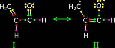
• An example is shown in fig.12.94 below:

Fig.12.94

This can be explained in 4 steps:
(i) I and II are resonance structures of the same molecule.
• In II, there are two formal charges, while in I, there are none.
• So I will be more stable than II
(ii) Consequently, the hybrid structure will have a greater resemblance to I than II.
• We can say:
Structure I will contribute more towards the hybrid structure.
(iii) We know that, any independent C atom will have four valence electrons.
• In II, we see that, the C atom of methyl branch has lost one of it’s electrons.
    ♦ That means, C has gained a +ve charge.
    ♦ Thus the formal charge of that C is ‘+’.
(iv) We know that, any independent O atom will have six valence electrons.
• In II, we see that, the O atom has gained one electron.
    ♦ That means, O has gained a -ve charge.
    ♦ Thus the formal charge of that O is ‘-’.

Rule 4:
    ♦ The resonance structure which has the -ve charge on more electronegative atom
    ♦ is more stable than
    ♦ The resonance structure which has the -ve charge on less electronegative atom.
• An example is shown in fig.12.95 below:

Fig.12.95

This can be explained in 4 steps:
(i) I and II are resonance structures of the same molecule.
• In II, the -ve charge is at the O atom. This is acceptable.
• In I, the -ve charge is at a C atom. This is also acceptable.
• But the -ve charge tends to be at a more electronegative atom. When O and C are compared, O is more electronegative.
• So II will be more stable than I
(ii) Consequently, the hybrid structure will have a greater resemblance to II than I.
• We can say:
Structure II will contribute more towards the hybrid structure.
(iii) We know that, any independent C atom will have four valence electrons.
• In I, we see that, the C atom of CH2 group has gained an electron.
    ♦ That means, C has gained a -ve charge.
    ♦ Thus the formal charge of that C is ‘+’.
(iv) We know that, any independent O atom will have six valence electrons.
• In II, we see that, the O atom has gained one electron.
    ♦ That means, O has gained a -ve charge.
    ♦ Thus the formal charge of that O is ‘-’.

Rule 5:
This is the reverse of rule 3.
    ♦ The resonance structure which has the +ve charge on more electropositive atom
    ♦ is more stable than
    ♦ The resonance structure which has the +ve charge on less electropositive atom.

Rule 6:
    ♦ The resonance structure in which 'distance between charges' is lesser
    ♦ is more stable than
    ♦ The resonance structure in which 'distance between charges' is greater.
• An example is shown in fig.12.96 below:

Fig.12.96 

• This can be explained in 3 steps:
(i) I and II are resonance structures of the same molecule.
• In I, the charges are close together (on adjacent atoms).
• In II, the distance between the charges is larger.
• So I will be more stable than II
(ii) Consequently, the hybrid structure will have a greater resemblance to I than II.
• We can say:
Structure I will contribute more towards the hybrid structure.
(iii) We know that, any independent C atom will have four valence electrons.
• In I, we see that, the first C atom from left has lost an electron.
    ♦ That means, C has gained a +ve charge.
    ♦ Thus the formal charge of that C is ‘+’.
• In I, we see that, the second C atom from left has gained an electron.
    ♦ That means, C has gained a -ve charge.
    ♦ Thus the formal charge of that C is ‘-’.
• In II, we see that, the first C atom from left has lost an electron.
    ♦ That means, C has gained a +ve charge.
    ♦ Thus the formal charge of that C is ‘+’.
• In II, we see that, the last C atom from left has gained an electron.
    ♦ That means, C has gained a -ve charge.
    ♦ Thus the formal charge of that C is ‘-’.

Rule 7:
Resonance structures which are equivalent, will have the same stability.
• An example is shown in fig.12.97 below:

Equivalent resonance structures make the same contribution towards hybrid structure.
Fig.12.97

• This can be explained in 3 steps:
(i) I and II are resonance structures of the same molecule.
If we rotate I about an axis passing through the CㅡH bond, we will get II.
(ii) We can apply any of the six rules written above. We will see that both are equivalent.
(iii) We know that, any independent O atom will have six valence electrons.
• In I, we see that, the bottom O atom has gained an electron.
    ♦ That means, O has gained a -ve charge.
    ♦ Thus the formal charge of that O is ‘-’.
• In II, we see that, the top O atom has gained an electron.
    ♦ That means, O has gained a -ve charge.
    ♦ Thus the formal charge of that O is ‘-’.

Solved example 12.18
Write the resonance structures of CH2=CHㅡCHO. Indicate the relative stability of the contributing structures.
Solution:
1. The three resonance structures are shown in fig.12.98 below:

Fig.12.98
  
2. First we apply rule 1:
(a) The number of bonds in I is 9
(b) The number of bonds in II is 8
(c) The number of bonds in III is 8
(d) Based on the number of bonds:
    ♦ I is more stable than II
    ♦ I is more stable than III
• So I is the most stable among the three.
3. Based on the number of bonds, II and III has the same stability.
• So we have to apply the other rules to find which one among II and III is more stable.
4. Applying rule 2, we get:
(a) In II, the first C (from left) has an incomplete octet. All other atoms have octet.
(b) In III, the O has an incomplete octet. All other atoms have octet.
(c) So applying rule 2, both II and III have the same stability.
• We have to apply the other rules.
5. Applying rule 3, we get:
(a) The number of formal charges in II is 2  
(b) The number of formal charges in III is also 2
(c) So applying rule 3, both II and III have the same stability.
• We have to apply the other rules.
6. Applying rule 4, we get:
(a) In II, the -ve charge is on the more electronegative atom, which is O
(b) In III, the -ve charge is on the lesser electronegative atom, which is C
(c) So applying rule 4, II is more stable than III
7. So the order of stability in the decreasing order is: I > II > III
• I makes the greatest contribution towards the hybrid structure.
• III makes the least contribution towards the hybrid structure.
• The hybrid structure will have more resemblance to I

Solved example 12.19
Explain why the following two structures I and II cannot be the major contributors to the real structure of CH3COOCH3

Fig.12.99

Solution:
1. In this problem, we are not asked to compare the two given structures. We are asked why both are not major contributors.
2. Consider I. The middle C atom do not have octet. So this structure cannot be a major contributor.
3. Consider II. A +ve charge is present on the lower O atom. This will make the structure very unstable because, O is highly electronegative. So this structure also cannot be a major contributor.

Solved example 12.20
Indicate the relative stability of the following resonance structures:

Fig.12.100
Solution:
1. First we apply rule 1:
(a) The number of bonds in I is 6
(b) The number of bonds in II is 5
(c) The number of bonds in III is 6
(d) Based on the number of bonds:
    ♦ I and III are more stable than II
• So the least stable structure is II.
2. Based on the number of bonds, I and III has the same stability.
• So we have to apply the other rules to find which one among I and III is more stable.
3. Applying rule 2, we get:
(a) In I, all atoms have octet.
(b) In III also, all atoms have octet.
(c) So applying rule 2, both I and III have the same stability.
• We have to apply the other rules.
4. Applying rule 3, we get:
(a) The number of formal charges in I is 2  
(b) The number of formal charges in III is also 2
(c) So applying rule 3, both II and III have the same stability.
• We have to apply the other rules.
5. Applying rule 4, we get:
(a) In I, the -ve charge is on the more electronegative atom, which is N
(b) In III, the -ve charge is on the lesser electronegative atom, which is C
(c) So applying rule 4, I is more stable than III
6. So the order of stability in the decreasing order is: I > III > II
• I makes the greatest contribution towards the hybrid structure.
• II makes the least contribution towards the hybrid structure.
• The hybrid structure will have more resemblance to I.


In the next section, we will see resonance effect.


Previous

Contents

Next

Copyright©2021 Higher secondary chemistry.blogspot.com


Tuesday, April 21, 2020

Resonance structures of Sulfur trioxide molecule and Nitrate ion

We were learning about resonance structures in section 4.9, We saw the examples of ozone molecule, carbon dioxide molecule and carbonate ion. In this section, we will see two more examples


Resonance structures of Sulfur trioxide


1. Let us first draw the Lewis dot structure of SO3 (Sulfur trioxide)
(We have seen the steps in an earlier section 4.2)
Step 1: Finding the number of dots
• Number of valence electrons of C = 6
• Number of valence electrons of O = 6
• So total number of valence electrons = [6+(3 × 6)] = 24
Step 2: The skeletal structure
• The skeletal structure is shown in fig.4.56(a) below:
Fig.4.56
Step 3: Preliminary single bonds
• The four atoms are joined by '─' as shown in fig.4.55(b) above
Step 4: Preliminary distribution of electrons
• First make the three outer O atoms octet
• This is shown in fig.c
• In the fig.c, we see that:
    ♦ The valence electrons of the O atoms are shown in green color
    ♦ The valence electrons of the C atom are shown in red color
• All the O atoms have 8 electrons (including the one red dot in the single bonds)
    ♦ So the three O atoms use up (3 × 8) = 24 electrons
    ♦ The number of remaining electrons = (24-24) = 0
• There are no more electrons to distribute
Step 5: Check for octet
• All the O atoms have got 8 electrons each
• The S atom has got only 6 electrons
    ♦ So this atom needs 2 more electrons
■ Rearrangement: Change the preliminary single bond
    ♦ Take a lone pair from the top O atom
    ♦ Using those electrons, change the top single bond to double bond as shown in the fig.d
• Now all atoms have octet
• The structure in fig.4.56(d) is stable
2. Another possible rearrangement
• We already know how to obtain the structure in fig.4.56(d) above
    ♦ We obtained it by working from fig.4.56(c)
• That same fig.4.56(c) is shown again in fig.4.57(c) below:
Fig.4.57
• Earlier, we took a pair from the top O atom
    ♦ This time, we take a pair from the left O atom and make a double bond
    ♦ This is shown in fig.4.57(d')
• The structure in fig.4.57(d') is stable
3. Yet another possible rearrangement
• We already know how to obtain the structure in fig.4.56(d) above
    ♦ We obtained it by working from fig.4.56(c)
• That same fig.4.56(c) is shown again in fig.4.58(c) below:
Fig.4.58
• Earlier, we took a pair from the top O atom
    ♦ This time, we take a pair from the right O atom and make a double bond
    ♦ This is shown in fig.4.58(d'')
• The structure in fig.4.58(d'') is stable
4. So we have three possible structures of SO3
    ♦ The structure in fig.4.56(d)
    ♦ The structure in fig.4.57(d')
    ♦ The structure in fig.4.58(d'')
• They are shown together in fig.4.59 below:
Fig.4.59
5. Now the next question arises:
■ In reality, which is the correct form in which SO3 exists? Fig.4.59 (d), (d') or (d'')?
• Let us try to find the answer:
(i) A S-O single bond will have a certain length
(ii) A S=O double bond will have a different length
(iii) With this information, we examine the bond lengths in an actual SO3 molecule
• Surprisingly, the actual values are different from (i) and (ii)
• In fact there are no 'values'. There is only one value
• The distance between S and O atoms in all the three pairs are the same
6. The structures in figs (d) (d') and (d'') are called canonical structures of SO3
• They are also called resonance structures of SO3
7. Resonance structures are indicated by giving double headed arrows between them

Resonance structures of nitrate ion

1. Let us first draw the Lewis dot structure of NO32- (nitrate ion)
(We have seen the steps in an earlier section 4.3)
Step 1: Finding the number of dots
• Number of valence electrons of N = 5
• Number of valence electrons of O = 6
• So total number of valence electrons = [5+(3 × 6)] = 23
• One extra electron is also present
■ We will write the number as two items:
    (a) Total number of ‘available valence electrons’ = 23
    (b) Number of electrons to be added = 1
• Final number =  [(a) ± (b)] = [(a) + (b)] = [23 + 1] = 24 
Step 2: The skeletal structure
• The skeletal structure is shown in fig.4.60(a) below:
Fig.4.60
Step 3: Preliminary single bonds
• The four atoms are joined by '─' as shown in fig.4.60(b) above
Step 4: Preliminary distribution of electrons
(Remember that, the 'available valence electrons' are distributed in this step)
• First make the three outer O atoms octet
    ♦ For that (3×8) = 24 electrons will be required
    ♦ But the number of 'available valence electrons' = 23
• So first, we will make the left and right O atoms octet 
• Then give the remaining electrons to the top O atom
• This is shown in fig.c
• In the fig.c, we see that:
    ♦ The valence electrons of the O atoms are shown in green color
    ♦ The valence electrons of the N atom are shown in red color
• Left and right side O atoms have 8 electrons (including the one red dot in the single bonds)
    ♦ So the two O atoms use up (2 × 8) = 16 electrons
    ♦ The number of remaining electrons = (23-16) = 7
    ♦ These 7 electrons are given to the top O atom
• There are no more electrons to distribute
Step 5: Check for octet
• The left and right side O atoms have got 8 electrons each
• The top O atom has got only 7 electrons
    ♦ So this atom needs 1 more electron
• The N atom has got only 6 electrons
    ♦ So this atom also needs 2 more electrons
■ Rearrangement: Change the preliminary single bond
    ♦ Take a lone pair from the top O atom
    ♦ Using those electrons, change the top single bond to double bond as shown in the fig.d
    ♦ Now the left and right side O atoms have octet
    ♦ The N atom also has octet
    ♦ But the top O atom has got only 7 electrons
• All the 23 electrons are used up. Still, complete octet is not achieved
• So, we will need an external electron
• Get one external electron from any suitable source
• Give it to the top O atom
• This is shown in fig.e
• Now all atoms have octet
(v) But the external electron will create a charge of -1
• So we put the structure inside square brackets and put a -1 at the top right corner
• The structure in fig.4.60(e) is stable
2. Another possible rearrangement
• We already know how to obtain the structure in fig.4.60(e) above
    ♦ We obtained it by working from fig.4.60(b)
• That same fig.4.60(b) is shown again in fig.4.61(b) below:
Fig.4.61
• Earlier, we made the left and right O atoms octet
    ♦ This time, we make the top and right O atoms octet. This is shown in fig.4.61(c')
• Next we take two electrons from the left O atom and make a double bond
    ♦ This is shown in fig.4.61(d')
• Finally, we add the extra electron to the left side O atom to attain octet
    ♦ This is shown in fig.4.61(e')
• The structure in fig.4.61(e') is stable
3. Yet another possible rearrangement
• We already know how to obtain the structure in fig.4.60(e) above
    ♦ We obtained it by working from fig.4.60(b)
• That same fig.4.60(b) is shown again in fig.4.62(b) below:
Fig.4.62
• Earlier, we made the left and right O atoms octet
    ♦ This time, we make the top and left O atoms octet. This is shown in fig.4.62(c'')
• Next we take two electrons from the right O atom and make a double bond
    ♦ This is shown in fig.4.62(d'')
• Finally, we add the extra electron to the right side O atom to attain octet
    ♦ This is shown in fig.4.62(e'')
• The structure in fig.4.62(e'') is stable
4. So we have three possible structures of NO3-
    ♦ The structure in fig.4.60(e)
    ♦ The structure in fig.4.61(e')
    ♦ The structure in fig.4.62(e'')
• They are shown together in fig.4.63 below:
Fig.4.63
5. Now the next question arises:
■ In reality, which is the correct form in which NO3- exists? Fig.4.63 (e), (e') or (e'')?
• Let us try to find the answer:
(i) A N-O single bond will have a certain length
(ii) A N=O double bond will have a different length
(iii) With this information, we examine the bond lengths in an actual NO3- ion
• Surprisingly, the actual values are different from (i) and (ii)
• In fact there are no 'values'. There is only one value
• The distance between N and O atoms in all the three pairs are the same
6. The structures in figs (e) (e') and (e'') are called canonical structures of NO3-
• They are also called resonance structures of NO3-
7. Resonance structures are indicated by giving double headed arrows between them


          Home


Copyright©2020 Higher Secondary Chemistry. blogspot.in - All Rights Reserved

Chapter 4.9 - Resonance Structures

In the previous section, we saw the basics about bond order. In this section, we will see resonance structures. We will explain it using some examples

Example 1: Resonance structures of ozone
1. Let us first draw the Lewis dot structure of O3 (ozone) molecule
(We have seen the steps in an earlier section 4.2)
Step 1: Finding the number of dots
• Number of valence electrons of O = 6
• So total number of valence electrons = (3 × 6) = 18
Step 2: The skeletal structure
• The skeletal structure is shown in fig.4.44(a) below:
Fig.4.44
Step 3: Preliminary single bonds
• The three atoms are joined by '─' as shown in fig.4.44(b) above
Step 4: Preliminary distribution of electrons
• First make the two outer O atoms octet
• Then give the remaining electrons to the central O atom
• This is shown in fig.c
• In the fig.c, we see that:
    ♦ The valence electrons of the outer O atoms are shown in green color
    ♦ The valence electrons of the central O atom are shown in red color
• Both the outer O atoms have 8 electrons (including the one red dot in the single bonds)
    ♦ So the number of electrons used up for making those O atoms octet = 16
    ♦ So the number of remaining electrons = (18-16) = 2
    ♦ These 2 electrons are given to the central O atom 
• There are no more electrons to distribute
Step 5: Check for octet
• Both the outer O atoms have got 8 electrons each. They have attained octet
• The central O atom has got only 6 electrons. It has not attained octet
• Thus, the preliminary distribution needs to be changed
■ Rearrangement:
• In fig.c, take a lone pair from the left side O atom
• Using those two electrons, convert the left side single bond to a double bond
• This is shown in fig.d
• In fig.d, all the atoms have octet. So it is a stable O3 molecule
2. Another possible rearrangement
• We already know how to obtain the structure in fig.4.44(d) above
    ♦ We obtained it based on fig.4.44(c)
• That same fig.4.44(c) is shown again in fig.4.45(c) below:
Fig.4.45
• In fig.4.45(c), take a lone pair from the right side O atom
• Using those two electrons, convert the right side single bond to a double bond
• This is shown in fig.4.45(d')
• In fig.d', all the atoms have octet. So it is also a stable O3 molecule
3. So we have two possible structures of O3
    ♦ One is the structure in fig.4.44(d)
    ♦ The other is the structure in fig.4.45(d')
• They are shown together in figs.4.46 below:
Fig.4.46
4. Now the next question arises:
■ In reality, which is the correct form in which O3 exists? Fig.4.46 (d) or (d')?
• The answer can be written in 5 steps:
(i) An O-O single bond will have a length of 148 pm.
    ♦ This is shown in figs.4.47(a) and (b) below.
(ii) An O=O double bond will have a length of 121 pm
    ♦ This is shown in figs.4.47(a) and (b) below.
(iii) With this information, we examine an actual O3 molecule.
    ♦ We would expect the distance between one pair of O atoms to be 148 pm
    ♦ We would expect the distance between the other pair of O atoms to be 121 pm
(iv) But surprisingly, the actual values are different from both 148 and 121
• In fact there are no 'values'. There is only one value. It is 128 pm
• The distance between atoms in both pairs is 128 pm.
• This is shown in fig.4.47(c) below:
Fig.4.47
• (a) and (b) are the two possible structures that we saw in fig.4.46
• (c) is different from both (a) and (b)
(v) Note the bonds in fig.c. They are neither single bonds nor double bonds
• This is indicated by the dashed lines
■ Fig.c represents the structure of O3 more accurately
5. The structures in (a) and (b) are called canonical structures
    ♦ They are also called resonance structures
(For some molecules, there will be more than two resonance structures)
6. Resonance structures are indicated by giving double headed arrows between them
• The structure in (c) is called the hybrid of the resonance structures
    ♦ It is also called the resonance hybrid

Example 2: Resonance structures of carbon dioxide
1. Let us first draw the Lewis dot structure of CO2 (carbon dioxide) molecule
(We have seen the steps in an earlier section 4.2)
Step 1: Finding the number of dots
• Number of valence electrons of C = 4
• Number of valence electrons of O = 6
• So total number of valence electrons = [4+(2 × 6)] = 16
Step 2: The skeletal structure
• The skeletal structure is shown in fig.4.48(a) below:
Fig.4.48
Step 3: Preliminary single bonds
• The three atoms are joined by '─' as shown in fig.4.48(b) above
Step 4: Preliminary distribution of electrons
• First make the two outer O atoms octet
• Then give the remaining electrons to the central C atom
• This is shown in fig.c
• In the fig.c, we see that:
    ♦ The valence electrons of the outer O atoms are shown in green color
    ♦ The valence electrons of the central O atom are shown in red color
• Both the outer O atoms have 8 electrons (including the one red dot in the single bonds)
    ♦ So the number of electrons used up for making those O atoms octet = 16
    ♦ So the number of remaining electrons = (16-16) = 0
• There are no more electrons to distribute
Step 5: Check for octet
• Both the outer O atoms have got 8 electrons each. They have attained octet
• The central C atom has got only 4 electrons. It has not attained octet
• Thus, the preliminary distribution needs to be changed
■ Rearrangement:
• In fig.c, take a lone pair from the left side O atom
    ♦ Using those two electrons, convert the left side single bond to a double bond
• Again, in fig.c, take a lone pair from the right side O atom
    ♦ Using those two electrons, convert the right side single bond to a double bond
• This is shown in fig.d
• In fig.d, all the atoms have octet. So it is a stable CO2 molecule
2. Another possible rearrangement
• We already know how to obtain the structure in fig.4.48(d) above
    ♦ We obtained it based on fig.4.48(c)
• That same fig.4.48(c) is shown again in fig.4.49(c) below:
Fig.4.49
• In fig.4.49(c), take two lone pairs from the left side O atom
• Using those four electrons, convert the left side single bond to a triple bond
• This is shown in fig.4.49(d')
• In fig.4.49(d'), all the atoms have octet. So it is also a stable CO2 molecule
3. Yet another possible rearrangement
• The above rearrangement in fig.4.49(d') was based on fig.4.48(c)
• That same fig.4.48(c) is shown again in fig.4.50(c) below:
Fig.4.50
• In fig.4.50(c), take two lone pairs from the right side O atom
• Using those four electrons, convert the right side single bond to a triple bond
• This is shown in fig.4.50(d'')
• In fig.4.50(d''), all the atoms have octet. So it is also a stable CO2 molecule
4. So we have three possible structures of CO2
    ♦ The structure in fig.4.48(d)
    ♦ The structure in fig.4.49(d')
    ♦ The structure in fig.4.50(d'')
• They are shown together in fig.4.51 below:
Fig.4.51
5. Now the next question arises:
■ In reality, which is the correct form in which CO2 exists? Fig.4.51 (d), (d') or (d'')?
• The answer can be written in 4 steps:
(i) A C-O single bond will have a length of 134 pm
(ii) A C=O double bond will have a length of 121 pm
(iii) A C≡O triple bond will have a length of 110 pm
(iv) With this information, we examine the bond lengths in an actual CO2 molecule
• Surprisingly, the actual values are different from 134, 121 and 110
• In fact there are no 'values'. There is only one value. It is 115 pm
• The distance between C and O atoms in both pairs is 115 pm
6. The structures in figs (d) (d') and (d'') are called canonical structures of CO2
• They are also called resonance structures of CO2
7. Resonance structures are indicated by giving double headed arrows between them


Example 3: Resonance structures of carbonate ion
1. Let us first draw the Lewis dot structure of CO32- (carbonate ion)
(We have seen the structure in an earlier section 4.3. But there we did not explore the various possible arrangements)
Step 1: Finding the number of dots
• Number of valence electrons of C = 4
• Number of valence electrons of O = 6
• So total number of valence electrons = [4+(3 × 6)] = 22
• Two extra electrons are also present
■ We will write the number as two items:
    (a) Total number of ‘available valence electrons’ = 22
    (b) Number of electrons to be added = 2
• Final number =  [(a) ± (b)] = [(a) + (b)] = [22 + 2] = 24 
Step 2: The skeletal structure
• The skeletal structure is shown in fig.4.52(a) below:
Fig.4.52
Step 3: Preliminary single bonds
• The four atoms are joined by '─' as shown in fig.4.52(b) above
Step 4: Preliminary distribution of electrons
(Remember that, only the 'available valence electrons' are distributed in this step)
• First make the three outer O atoms octet
    ♦ For that (3×8) = 24 electrons will be required
    ♦ But the number of 'available valence electrons' = 22
• So first, we will make the left and right O atoms octet 
• Then give the remaining electrons to the top O atom
• This is shown in fig.c
• In the fig.c, we see that:
    ♦ The valence electrons of the O atoms are shown in green color
    ♦ The valence electrons of the C atom are shown in red color
• Left and right side O atoms have 8 electrons (including the one red dot in the single bonds)
    ♦ So the two O atoms use up (2 × 8) = 16 electrons
    ♦ The number of remaining electrons = (22-16) = 6
    ♦ These 6 electrons are given to the top O atom
• There are no more electrons to distribute
Step 5: Check for octet
• The left and right side O atoms have got 8 electrons each
• The top O atom has got only 6 electrons
    ♦ So this atom needs 2 more electrons
• The C atom has got only 6 electrons
    ♦ So this atom also needs 2 more electrons
■ Rearrangement: Change the preliminary single bond
    ♦ Change the top single bond to double bond as shown in the fig.d
• Two electrons from the top O is used for making the new bond
    ♦ Now the left and right side O atoms have octet
    ♦ The C atom also has octet
    ♦ But the top O atom has got only 6 electrons
• All the 22 electrons are used up. Still, complete octet is not achieved
• So, we will need external electrons
• Get two external electrons from any suitable source
• Give them to the top O atom
• This is shown in fig.e
• Now all atoms have octet
(v) But the two external electrons will create a charge of -2
• So we put the structure inside square brackets and put a -2 at the top right corner
• The structure in fig.4.52(e) is stable
2. Another possible rearrangement
• We already know how to obtain the structure in fig.4.52(e) above
    ♦ We obtained it by working from fig.4.52(b)
• That same fig.4.52(b) is shown again in fig.4.53(b) below:
Fig.4.53
• Earlier, we made the left and right O atoms octet
    ♦ This time, we make the top and right O atoms octet. This is shown in fig.4.53(c')
• Next we take two electrons from the left O atom and make a double bond
    ♦ This is shown in fig.4.53(d')
• Finally, we add the extra two electrons to the left side O atom to attain octet
    ♦ This is shown in fig.4.53(e')
• The structure in fig.4.53(e') is stable
3. Yet another possible rearrangement
• We already know how to obtain the structure in fig.4.52(e) above
    ♦ We obtained it by working from fig.4.52(b)
• That same fig.4.52(b) is shown again in fig.4.54(b) below:
Fig.4.54
• Earlier, we made the left and right O atoms octet
    ♦ This time, we make the top and left O atoms octet. This is shown in fig.4.54(c'')
• Next we take two electrons from the right O atom and make a double bond
    ♦ This is shown in fig.4.54(d'')
• Finally, we add the extra two electrons to the right side O atom to attain octet
    ♦ This is shown in fig.4.54(e'')
• The structure in fig.4.54(e'') is stable
4. So we have three possible structures of CO32-
    ♦ The structure in fig.4.52(e)
    ♦ The structure in fig.4.53(e')
    ♦ The structure in fig.4.54(e'')
• They are shown together in fig.4.55 below:
Fig.4.55
5. Now the next question arises:
■ In reality, which is the correct form in which CO32- exists? Fig.4.55 (e), (e') or (e'')?
• The answer can be written in 3 steps:
(i) A C-O single bond will have a length of 134 pm
(ii) A C=O double bond will have a length of 121 pm
(iii) With this information, we examine the bond lengths in an actual CO32- molecule
• Surprisingly, the actual values are different from 134 and 121
• In fact there are no 'values'. There is only one value. It is 128 pm
• The distance between C and O atoms in all the three pairs is 128 pm
6. The structures in figs (e) (e') and (e'') are called canonical structures of CO32-
• They are also called resonance structures of CO32-
7. Resonance structures are indicated by giving double headed arrows between them

• We will practice using 2 more examples: SO3 and NO3-
    ♦ The steps can be seen here

■ Now we can write the definition of resonance structures. It can be written in 3 steps:
(i) Sometimes, a single Lewis structure cannot describe a molecule accurately
• We may have to show two or more structure
(ii) Those structures will have similar energies
• Also positions of atoms will be similar in those structures
• But 'lone pairs' and 'bonds' will be different
• Those structures are called canonical structures or resonance structures
(iii) None of the resonance structures can be used to represent the actual structure
• The actual structure is more accurately described by a structure called hybrid of the resonance structures
• This structure is also called the resonance hybrid

■ We must always remember two important points related to resonance:
1. Resonance stabilizes the molecule as the energy of the resonance hybrid is less than the energy of any single resonance structure
• This can be explained in 5 steps:
(i) Consider a resonance hybrid and it’s various resonance structures 
(ii) Each of the resonance structures will have it’s own ‘quantity of energy’
(iii) The resonance hybrid will also have it’s own ‘quantity of energy’
(iv) The energy in (iii) will be less than any of the energies in (ii)
(v) So the 'phenomenon of resonance' helps the molecule to attain greater stability 
2. Resonance averages the bond characteristics as a whole
• This can be explained in 6 steps:
(i) We have seen some of the bond characteristics:
Bond length, Bond angle, Bond enthalpy, Bond order
(ii) Take any one of them, say bond length
(iii) Each of the resonance structures will have 'it’s own bond lengths' for it’s various bonds
(iv) The resonance hybrid will also have 'it’s own bond lengths' for it’s various bonds
(v) The values in (iv) will be the averages of the corresponding values in (iii)
(vi) Here, we have considered bond length. The same can be written about other bond characteristics also

Many misconceptions are associated with resonance. We will analyze four misconceptions and get to know the facts
1. The existence of resonance structures in a sample
• This can be analysed in 3 steps:
(i) Let us take the example of ozone
    ♦ We saw that there are 2 resonance structures for ozone
(ii) Take any sample of ozone
• The fact is that, we will never find any of those two resonance structures in any ozone sample
(iii) The resonance structures exist only in drawings. The true structure is the hybrid of those resonance structures
2. The existence of resonance structures based on time
• This can be analysed in 3 steps:
(i) Let us take the example of ozone
    ♦ We saw that there are 2 resonance structures for ozone
(ii) Take any sample of ozone
• There is a popular belief:
    ♦ At some instances of time, the sample will contain the O3 molecules in one canonical form
    ♦ At some other instances of time, the sample will contain the O3 molecules in the other canonical form
(iii) This is totally wrong
• At any instant that we take, there will be only one form, which is the hybrid
3. Equilibrium between various canonical forms
• This can be analysed in 3 steps:
(i) Let us take the example of ozone
    ♦ We saw that there are 2 resonance structures for ozone
(ii) Take any sample of ozone
• There was a popular belief:
    ♦ The sample contains both the canonical forms in equal quantities
    ♦ If one canonical form is in excess quantity, it will be gradually converted into the other form
          ✰ This conversion will continue until both forms are in equal quantities
(iii) This is totally wrong
• The canonical forms do not even exist. So there is no question of attaining an equilibrium between them
4. Representation of the molecule
• This can be analysed in steps:
(i) Let us take the example of ozone
    ♦ We saw that there are 2 resonance structures for ozone
(ii) One may think that he/she can represent the O3 by drawing 'any one' of it's Lewis structures
(iii) But the fact is this:
• If we draw just any one, we will be conveying the 'wrong information' that, one bond in O3 is a single bond and the other is a double bond
(iii) It is impossible to represent such molecules by a single Lewis dot structure
• So it is compulsory to draw all the canonical structures and show double headed arrows between them


Now we will see a solved example
Solved example 4.5
H3PO3 can be represented by structures (a) and (b) shown in fig.4.64 below. Can these two structures be taken as the canonical forms of the resonance hybrid representing H3PO3 ?
Fig.4.64
If not, give reasons for the same.
Solution:
In the two given structures, the positions of atoms are not the same. So they are not the canonical forms of the resonance hybrid representing H3PO3

In the next section, we will see polarity of bonds

PREVIOUS           CONTENTS          NEXT


Copyright©2020 Higher Secondary Chemistry. blogspot.in - All Rights Reserved